36v TCM Electric Fork Lift Battery Revival Diagnostics Guide

Collapse

Forum Announcement

Collapse
No announcement yet.
X
 
  • Filter
  • Time
  • Show
Clear All
new posts

  • 36v TCM Electric Fork Lift Battery Revival Diagnostics Guide

    Hey everyone, it's been a while! I’ve been busy with other projects, but I finally pulled an electric forklift into the shop to start diagnosing its battery system.

    IMG_2836.jpg


    It’s always great to get back to working on electric vehicles because, at the core, electric forklifts, golf carts, and most other EVs share a lot of the same fundamental components. Whether you're looking at a golf cart cruising around a course, an electric pallet jack in a warehouse, or even a modern EV on the road, they all operate on the same basic principles. The key systems, battery packs, controllers, contactors, solenoids, and drive motors, are nearly identical, just scaled to different power levels.

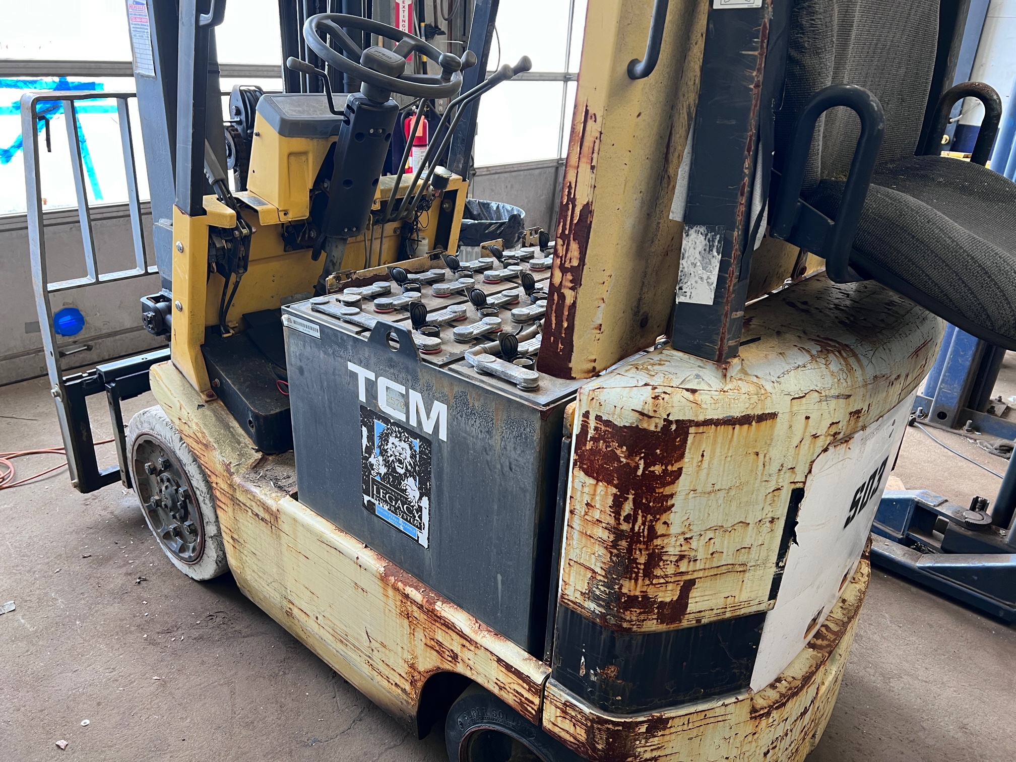
    The electric forklift I’m working on today runs on a 36V battery system, just like many older golf carts, but there’s a key difference in how that voltage is achieved. Instead of using six 6V batteries or three 12V batteries like in a golf cart, this forklift has 18 individual 2V cells wired in series to create the full 36V pack. This type of setup is common in industrial equipment because large 2V cells provide much more consistent performance compared to smaller multicell batteries. However, when they sit for extended periods, they can become severely discharged, which is exactly the case here.

    IMG_2841.jpg

    When this forklift came into the shop, the battery pack was reading around 0.15V per cell, which is about as dead as it gets. That means the entire pack was sitting at barely over 2-3 volts when it should be over 36V fully charged. The good news? It’s not at absolute zero, which means there’s still a slim chance of revival. Batteries that have been sitting for years with zero voltage are much harder to bring back, as deep sulfation and internal damage can make them nearly impossible to recover. Since this pack still holds a tiny amount of charge, we at least have something to work with.

    IMG_2846.jpg

    Right now, the goal is to get it over 36V so we can run basic tests on the forklift’s powertrain and see if the electrical system is functional. Since it didn't come with a charger, to do this I’m using a simple 12V car charger, carefully bringing the cells up in small increments. This isn’t a long term way to charge a full industrial pack, but at this stage, we just need enough voltage to wake the system up and test the main contactor, controller, and motor circuits.

    I’ll keep updating with what we find, whether the batteries have any life left in them or if we’ll need to swap them out, plus what kind of shape the forklift’s drive system is in once we get it powered up. If you’ve worked on something similar, feel free to chime in!​​

    Photos Attached

    You do not have permission to view this gallery.

    If you are a guest, you may be required to Log In or Sign Up to view.

    This gallery has 1 photos.

    Updated by Michael Eddie; last week.
    Regards

  • #2
    Since we’ve got some initial voltage into the battery pack and confirmed there’s still some life in it, it’s time to map out the pack and set up a proper charging plan.

    The forklift’s battery system consists of 18 individual 2V cells, all wired in series to create the full 36V pack. To simplify charging and diagnostics, we’ve identified them into three 12V sections, each containing six 2V cells. By doing this, we can charge and monitor the batteries in smaller sections, which helps prevent overloading any single group and ensures each section is getting the proper attention.

    layout.jpg

    A general rule of thumb for battery charging is to charge at 20% of the battery pack’s amp hour (Ah) capacity. In this case, our forklift’s battery pack is rated at 935Ah. Since we’re dividing it into three 12V sections, we need to determine the appropriate charge rate for each section:
    1. 935Ah ? 3 sections = ~311.6Ah per 12V section
    2. 20% of 311.6Ah = ~62A charge rate per section

    This means that ideally, each 12V group should be charged at around a maximum of 62 amps for a proper and efficient charge cycle. Of course, most conventional chargers won’t output exactly 62A, so we’ll work with what we have while keeping an eye on voltage and heat buildup to avoid overstressing the cells.

    IMG_2842.jpg

    Now that we have the battery pack properly mapped and our target charge rate calculated, we can move forward with charging. Since these batteries were at 0.15V per cell initially, our goal is to gradually bring them back up to a safe voltage. We’ll use a DVM to closely monitor the voltage, checking for any signs of imbalance, such as one cell rising significantly faster than the others.

    layout2.jpg

    Additionally, we’ll keep an eye on individual cell temperatures, if any cells start getting hotter than the rest, that’s an early warning sign of internal resistance or potential failure. If we notice major discrepancies in voltage between cells, we may need to go in and equalize charge certain sections separately to bring everything back in line. And of course, monitor water levels. These cells were really low, and we ended up having to add about 5 gallons of distilled water in total from the start.

    If all goes well, we should soon have enough voltage to start running real diagnostics on the powertrain. More updates to come as we move forward!
    Regards

    Comment


    • #3
      layout2.jpg
      Group 1

      layout3.jpg
      Group 2

      layout4.jpg
      Group 3

      After charging each of the three 12V groups at 65 amps for about 12 hours each, we let the batteries settle for a few hours. Now, we’re reading around 1.94V per cell, 11.79V per group, and about 35.3V for the entire pack. While this is technically under 50% state of charge, it’s still a good place to be for testing purposes because we’re now seeing some real signs of life in the system. The fact that the voltage is holding steady indicates that the cells are accepting charge and aren’t completely shot, this is important because if the pack had severe internal damage, we’d be seeing extreme voltage dropoffs by now.

      IMG_2843.jpg
      IMG_2844.jpg
      IMG_2851.jpg

      With the pack holding a charge, we decided to start testing some of the forklift’s key electrical functions. The first good sign? The lights work. This tells us that the 36V to 12V DC converter is functional, meaning the forklift’s low voltage accessories are getting power. Next, we tested the solenoid, and sure enough, it clicks on power up, a promising indicator that the control system is engaging.

      IMG_2854.jpg

      But when we pressed the accelerator pedal, something wasn’t right. Instead of the expected engagement of the drive system, we heard nothing but a soft tick, almost like a relay trying to fire but losing connection. This pointed to a potential voltage drop or a loose connection somewhere in the main power circuit.

      After some investigating, we found the culprit: the main power plug connecting the battery pack to the forklift had a loose ground cable. Over the years, repeated plugging and unplugging had caused the negative ground wire to slowly work itself loose, leading to an inconsistent connection. It makes sense, without a solid ground, the whole system struggles to maintain proper electrical flow.

      IMG_2861.jpg

      To fix this, we:
      1) Resoldered the ground connection, ensuring a solid electrical bond.
      2) Added a pull strap to the connector, preventing future strain and reducing the risk of this happening again.

      IMG_2839.jpg

      With the main power connection restored, we’re now ready for a real round of testing. However, given that our battery pack is sitting just over 35V, we want to boost it slightly above 36V to eliminate any potential low voltage cutoffs during testing. To do this, we’re connecting an auxiliary battery pack to supplement the main system, effectively giving the forklift a temporary voltage boost to stabilize power delivery while we diagnose the drivetrain.

      This is where things start to get interesting, now that we have a functional battery pack and power flowing properly, we can begin diagnosing the forklift’s powertrain. Will the motor spin up? Will the controller respond as expected? Stay tuned, because next up, we put the drive system to the test!
      Updated by Michael Eddie; 6 days ago.
      Regards

      Comment


      • #4
        With the batteries now charged up as much as we can safely get them for the moment, it's the perfect time to run a few major component tests before we finalize the tally on cost, repairs, and next steps for this electric forklift.

        To help bring our system voltage up to a more functional level, we’ve temporarily added two auxiliary 12V batteries, one connected in parallel with Group 1 and the other with Group 3 of our main pack. With that setup, we're currently sitting at a solid 37.3 volts which is plenty to run tests on this forklifts core systems.

        IMG_2845.jpg

        First up was the hydraulic system which powers the 3 tier mast. In electric forklifts, this system is typically controlled by a DC hydraulic pump that pulls power from the main battery pack and sends pressurized fluid to a series of cylinders and directional control valves. One valve routes flow to raise the rack, while another manages the tilt function pivoting the mast forward and backward. Sure enough, with 37.3V, the pump came to life, and the mast raised smoothly through all three stages and tilted as it should. No odd noises, no jerky motion, just solid, responsive action. That alone tells us the hydraulic pump, valves, and lift controls are healthy.

        IMG_2857.jpg


        Next, we tested drive functionality. With the solenoid clicking in, we pressed the accelerator and were happy to discover the forklift moved smoothly in both forward and reverse. Electric forklifts like this use a DC series motor paired with a controller that modulates voltage and current to the motor based on throttle input. Everything checked out, we’re seeing typical low speed operation, which is expected given our battery voltage is just under ideal, but it’s moving under its own power and that’s a major milestone. The contactors are engaging, and the motor is responding properly, which is exactly what we want to see at this stage.


        With the lift, tilt, and drive functions all passing initial tests, and after a quick powerwash, we’re looking at a very restorable machine. The next step is getting a set of forks mounted, and luckily, I may have a spare set laying around. Once those are on, we’ll put it through some light duty paces on a workday to see how it handles under real world conditions, just enough to assess how well it holds up under load and whether any hidden issues start to reveal themselves.

        IMG_2866.jpg

        Overall this is shaping up to be one of those fun revival projects, the kind where a machine that looked like it was long past its prime starts to breathe again. It’s also a great reminder of how interconnected electric systems are, and how a few careful steps like mapping batteries, identifying weak points, and creatively applying power can bring something back to life.

        If you’ve got similar equipment sitting around or are thinking about diving into a battery powered rehab project, stick around. We’ll be digging deeper in the next updates and maybe even hauling a few loads before long. Stay tuned!
        Regards

        Comment

        Show More Comments

        Unconfigured Ad Widget

        Collapse

        Unconfigured Ad Widget

        Collapse
        Loading
        X