How to identify, inspect and begin restoring a non running Club Car golf cart

Collapse

Forum Announcement

Collapse
No announcement yet.
X
 
  • Filter
  • Time
  • Show
Clear All
new posts

  • How to identify, inspect and begin restoring a non running Club Car golf cart

    This is for anyone who’s ever found themselves staring at a dusty, tired looking golf cart and thinking “Alright, what’s the story here?” We’ve got an electric Club Car on our hands and we’re about to walk it back from wherever it’s been sitting to moving under its own power again.


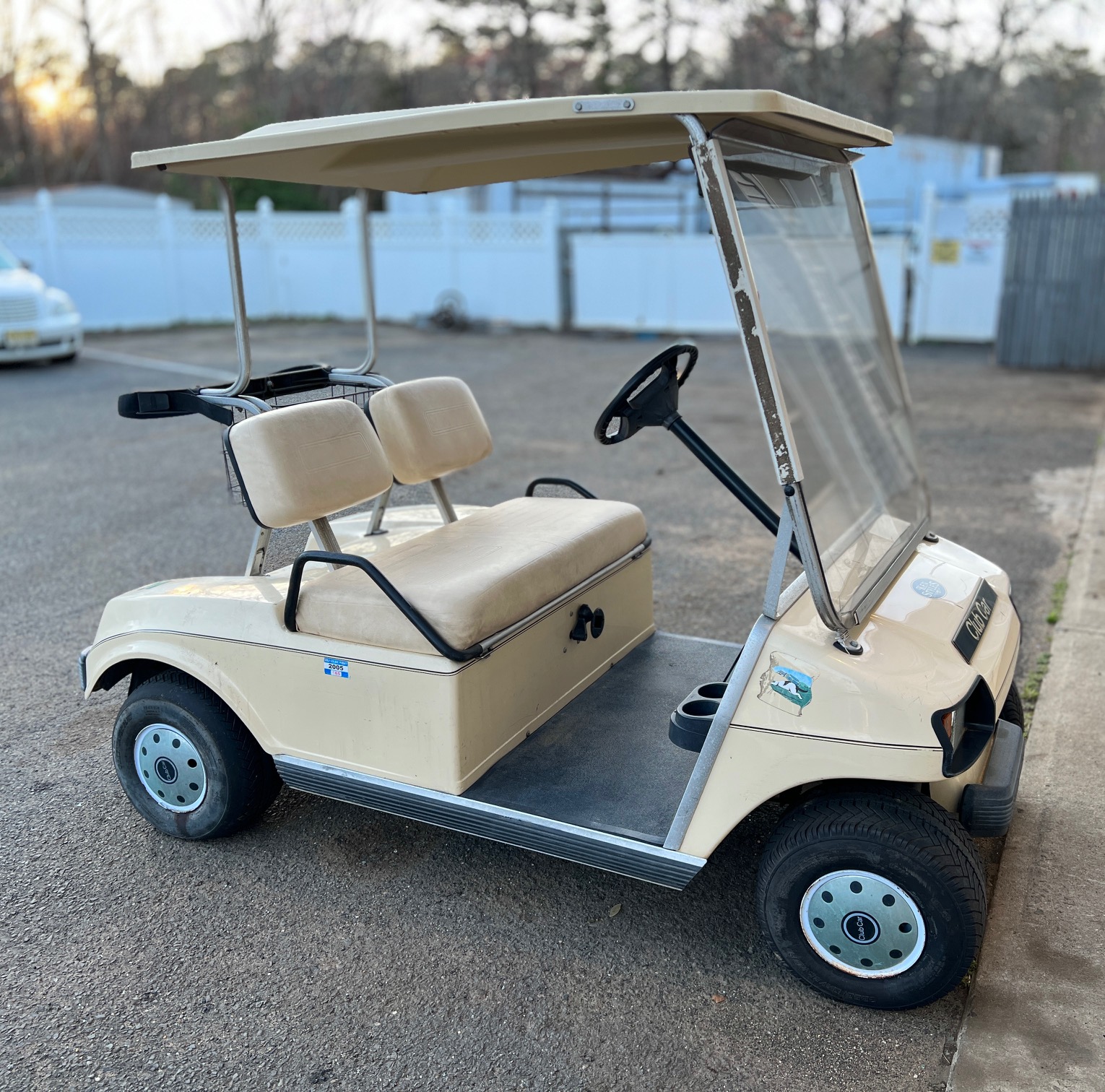
    For Club Car carts, the serial number is our golden ticket to knowing exactly what we’re dealing with. You’ll usually find it under the passenger side dash on the lower edge, either stamped into a small aluminum plate or on a decal. It gives us the model, the year and sometimes even build details.

    Even just from the photo we can begin to gather clues about the cart’s health and history. For instance, take a look at the condition of the tires. Uneven wear tells us about potential alignment issues, while dry rot might suggest it’s been sitting out in the sun for a few seasons. Faded plastics or a chalky body finish often indicate long term exposure to UV, while corroded battery terminals are a quick sign we’ll be dealing with voltage drops and connection issues down the line. If there is any suspension sag, worn or cracked seat cushions, missing access panels, each of these speaks to how the cart’s been treated. These aren’t just cosmetic, they’re breadcrumbs leading to bigger mechanical truths.

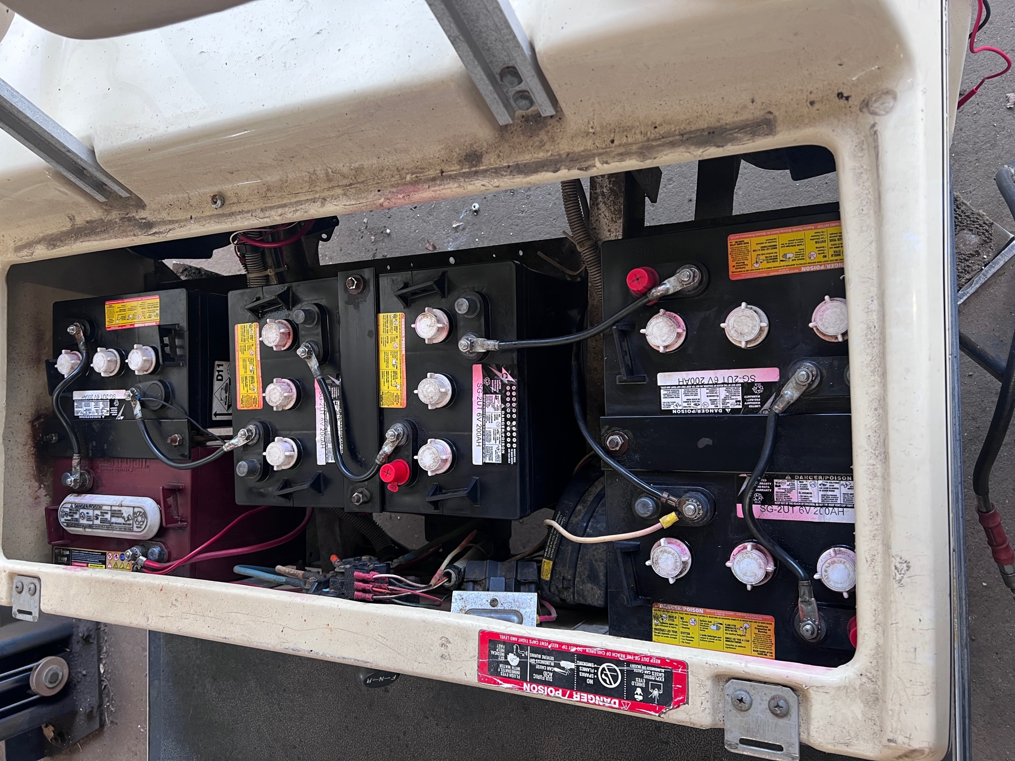
    From here, our goal is to dig just deep enough to form a smart game plan. We’re going to start with battery evaluation, checking the condition and voltage of each unit, whether it’s a 36V or 48V system. From there, we’ll map out the main power circuit, batteries, cables, solenoid to make sure current is flowing where it needs to. If it’s a series cart, we’ll explain what that means for power delivery and throttle input. If it’s a regen cart with IQ or Excel, we’ll walk through the role of the speed controller and how it interacts with components like the MCOR or V-Glide, depending on the drive system and year.

    There’s a lot to uncover and we’ve only taken the first look. Next up we get into power, connections, and what this cart tells us when we finally get to lift the seat and look!

    Photos Attached

    You do not have permission to view this gallery.

    If you are a guest, you may be required to Log In or Sign Up to view.

    This gallery has 1 photos.

    Updated by Michael Eddie; last week.
    Regards

  • #2
    From the attached guide and visual cues, we’ve identified this cart as a Club Car DS model, a classic platform that’s been around since the early 1980s. The DS name comes from Dom Saporito, one of Club Car’s original designers, and was in production for decades.

    Now taking a closer look at the serial number plate, we’re in good shape, the tag appears to be original, unmodified, and still securely intact, which is a welcome sight. Club Car serial numbers are typically found on the passenger side, just below the dash area, often on a small aluminum tag riveted to the frame or dashboard support panel. The plate we’re looking at doesn't show signs of tampering or replacement which gives us high confidence that we're working with the original manufacturing data.

    IMG_3057.jpg

    Here’s where it gets interesting about serial numbers. Club Car like other major manufacturers occasionally takes carts back in for factory refurbishment or remanufacture, especially after long term lease returns from golf courses. When this happens, the original serial number tag is usually removed and replaced with a generic “Refurbished” or “Remanufactured” tag, often lacking the standard serial decoding format. These replacement tags cannot be decoded the same way as the original factory tags, which makes it harder to verify the model year and specs at a glance. If you ever come across one of these, your best bet is to look elsewhere on the cart for an original number, sometimes stamped on the frame rails beneath the seat, or behind the storage pockets on the dash. In extreme cases, contacting Club Car directly with your details and a few photos may help them pull up internal records.

    Fortunately for us, our DS still has its factory original serial number which we can plug into our Club Car serial number decoder to get accurate information about the year and configuration.

    IMG_3056.jpg

    Right here it looks like we have a 1994 Club Car DS Electric on our hands. So with this info decoded we know exactly what we’re dealing with and that’s going to make the next steps a whole lot smoother. Up next, we’re going to lift the seat and take our first real look into the battery bay, cabling, and power delivery system and setup. We’ll start mapping connections, inspecting for corrosion, and laying the groundwork for a full diagnosis.

    Photos Attached

    You do not have permission to view this gallery.

    If you are a guest, you may be required to Log In or Sign Up to view.

    This gallery has 1 photos.

    Updated by Michael Eddie; last week.
    Regards

    Comment


    • #3
      This is the point where the cart starts opening up and telling its story, and let me just say, it’s already a pretty interesting one.

      First thing noticed the moment the seat came up is that each of the six battery's have three fill caps. That is a dead giveaway that we’re looking at 6 volt batteries, and with six of them wired in series, that means we’ve got a 36V system on our hands. This makes sense. The 36V Club Car DS models were primarily built prior to the late 90s especially in base models or fleet carts. This fits nicely with the serial number data we gathered earlier and gives us a solid frame of reference when we start diving deeper.


      Now the second big thing we laid eyes on was a V-Glide. This is one of Club Car’s early throttle input systems and it uses a multi contact wiper arm and a series of resistors to send varying voltage signals to the powertrain. Depending on year and setup, some DS models paired this with a resistor coil drive system, but in our case, a quick peek deeper revealed something even better. A solid state speed controller sitting just behind the battery tray. That’s a great find. The presence of a Curtis style controller opens up possibilities, if we ever decide to go lithium down the road, this cart is already half prepped for a modern retrofit. No need to rip out resistor coils or deal with primitive throttle mappings. We’re looking at a cart with upgrade flexibility which is a major win.

      IMG_3059.jpg

      IMG_3060.jpg

      First order of business: clean all battery connections, tighten them down, and give the whole battery bay a deep clean. The pics earlier show what we started with, caked on grime, corrosion building up on terminals, and just general battery neglect. It’s not uncommon in carts that have been sitting for a few years. But after some elbow grease, baking soda, and contact cleaner, we’ve got it looking like a completely different machine. A clean, dry bay with solid connections and a fresh foundation to build on.


      Along the way, we spotted a few things. The solenoid is just dangling by its wires, not mounted at all. That’s a no-go for long term operation and could explain the inop condition if it was ever powered on like this. We’ll need to jump over to our diagrams section, grab the proper schematic for this setup, and verify all power and control wires, especially solenoid wiring which at first glance already appears off. The 250 ohm precharge resistor is hanging by a thread, literally, so we’ll need to properly reconnect or replace that to prevent voltage spikes to the controller on startup. That alone can make or break your controller health.

      IMG_3061.jpg

      We also spotted some butt connectors in the wiring near the V-Glide and reverse buzzer, not necessarily a red flag but worth keeping an eye on. No signs of incorrect routing just yet, but we’ll give it a closer inspection once we pull the wiring loose for visual checks.

      As of now, with everything cleaned up and buttoned down, we’re sitting at 22.5V across the pack. That’s low, but not dead. We’re going to try and push a 40-60 amp charge into these batteries one pair at a time to wake them up a bit, see if they’ll take a surface charge and hold long enough for us to run functional tests.

      Photos Attached

      You do not have permission to view this gallery.

      If you are a guest, you may be required to Log In or Sign Up to view.

      This gallery has 1 photos.

      Updated by Michael Eddie; last week.
      Regards

      Comment


      • #4
        Check out the wiring diagram, I'm attaching the PDF to this post, the first thing that jumps out is something that’s not there. A Run/Tow switch. The Run/Tow switch is typically a small toggle switch located in the battery bay usually found on the controller side of the cart. You’ll see it on regen (regenerative braking) systems. Its job is to isolate the controller cutting power to prevent damage during maintenance or towing. When you see that switch in a cart, you’re looking at a system that’s controller regulated with regenerative braking and speed sensors.

        But our diagram and the cart don’t have that switch, which tells us we’re working with an older series drive system. Series systems don’t have regen braking, don’t need a tow mode, and are far simpler overall in terms of control logic. Instead of a controller that talks to a motor with feedback loops and throttle maps, you’ve got a V-Glide or multi-step throttle feeding signal directly into a Curtis style speed controller, which then sends power to the motor via the solenoid. It’s raw, direct, and just about bulletproof if you maintain it. You press the pedal, and power flows, no delay, no digital curve. It’s why some folks still prefer these setups for simple utility builds or carts used in an environment where less tech means more reliability.

        So now that we’ve confirmed we’re working with a Series system, let’s talk about what that means for the motor. Club Car DS carts with series setups are equipped with a series wound DC motor, which differs from the separately excited (sepex) motors used in regen setups like Club Car's IQ or Excel systems. Series motors are known for their high torque at low speeds and work best for hauling, hunting, and hill climbing. Tasks where raw pulling power matters more than top end speed. These motors are simple in construction and wiring, two wires for power in, and they’re ready to spin.

        Compare that to a sepex motor, which requires four connections, two for the armature, and two for the field windings and works in conjunction with a controller that modulates both sides independently. Sepex motors shine in speed and regenerative braking with smoother throttle response and automatic braking/recharging when you let off the pedal. IQ carts with these setups are usually preferred for neighborhood cruisers.

        Back to our cart, the series motor we’ve got is ideal for a platform intended to pull small trailers or drive on soft dirt roads. It’s less picky about programming, doesn’t require speed sensors and responds well to basic upgrades like bigger tires, thicker cables or higher amp controllers. It won’t run as fast as an IQ cart and it doesn’t have regen braking, but what it does have is simplicity, which, if you’re planning to keep things low maintenance, is a big win.
        Attached Files:
        Free Download, courtesy of Golf Carts Forum

        Photos Attached

        You do not have permission to view this gallery.

        If you are a guest, you may be required to Log In or Sign Up to view.

        This gallery has 1 photos.

        Updated by Michael Eddie; last week.
        Regards

        Comment


        • #5
          IMG_3079.jpg

          Alright, we’ve been at this for a while now and we finally got pack voltage up to 38.5V by charging the 6V batteries in pairs using a 12V car charger running around 40-65 amps, pushing each pair until they were warm (not boiling), just enough for the original Lester 13000 charger to recognize the voltage and take over. That in itself felt like a small win. But like many things in life, the celebration was short lived. Once we removed the charging source, voltage began dropping like a rock. Rapidly. A few minutes later, we were just barely sitting above 36V. Not ideal.

          Viewing each battery individually gave us the bad news. Three of the six batteries are clearly really struggling, holding voltage for only seconds before self discharging on their own. And wouldn't you know it, one of the three others is already a Trojan. Classic sign of a past attempt to fix things with just one new battery, which as we know, is a Band Aid on a broken axle. A mismatched pack like this is almost guaranteed to cause erratic performance and low voltage symptoms, poor acceleration, clicking solenoids but no drive, or carts that go 50 feet and die, starts to make perfect sense.

          But the real star of today’s show is our wiring cleanup and solenoid mapping which needed immediate attention. As mentioned before, the solenoid was just hanging loose when we lifted the seat, a red flag if there ever was one. On closer inspection, things weren’t just messy, they were flat out wired wrong. Both the positive and negative small post wires were connected to the same solenoid terminal, with just the diode bridging the two small posts. That's a big problem. At best, the solenoid never functions properly, at worst, you're back feeding current where it doesn't belong and risking damage to the controller or microswitches. I immediately disconnected all solenoid wiring before doing any charging, safety first like we didn’t knowingly need components on the casualty list. Here is a pic of the wrong wiring mess for those curious:

          IMG_3066.jpg

          Fast forward to rewiring, we removed and tested the diode with our DVM’s diode function, confirmed the proper direction (stripe toward the positive small post), and reinstalled it across the terminals. On this system, the yellow wire is ground, so thats considered the negative small post, and the other small post gets the positive input from the microswitch. With the diode and microswitch circuit wired properly, it was time to reconnect the precharge resistor (which had previously been hanging by a thread) and install the large solenoid cables. On this cart, one large terminal connects to the main positive pack lead and the other goes to B+ on the controller.

          Pics of proper solenoid wiring, location and mounting:
          IMG_3072.jpg
          IMG_3075.jpg

          With everything connected and pack voltage back over 36V, we did a "key off" test and heard the V-Glide microswitch clicking, a good sign that throttle input will trigger the control circuit. With the key on, shifter in Forward, and the pedal down, we got a solenoid click. But, no wheel movement.

          Strange. The solenoid was clicking. The controller appeared to be sending power. Our DVM already on the pack showed significant voltage drop when pressing the pedal, indicating the controller was likely delivering power to the motor. We previously visually inspected the wiring, motor leads, controller outputs, all clean and undisturbed. Nothing looked burned, loose, or tampered with.

          IMG_3076.jpg

          We’re standing there scratching our heads, one of us on the throttle, and I’m looking at the motor housing thinking, what do I have to lose? I grab the mini sledge (because, of course, we have one within arm’s reach), and with just a few controlled taps to the steel motor housing, the magic happens. The motor growls to life, wheels move forward, and that old motor turns for the first time in who knows how long.

          From there, it was time to validate systems. Reverse function? Check. Throttle response? Confirmed. Voltage drop? Yeah, still not great. The weak batteries just don’t have the reserve to keep things going. But we’ve proven the cart works, and the Curtis 1204 is alive, which is a huge box to check.

          Right now we’re considering swapping in three brand new 12V batteries as a cheap option just to get rolling under full conditions. Not ideal if you're looking for longer range, but with the Lester charger working, it’ll keep the cart breathing while we plan for a future battery solution maybe even lithium.

          This cart isn’t showroom ready, but for something that was DOA a week ago, we’re breathing new life into it. Once the new batteries are in, we’ll be verifying charging input, controller response, brake system, and checking for any sneaky gremlins still hiding.
          Regards

          Comment

          Show More Comments

          Unconfigured Ad Widget

          Collapse

          Unconfigured Ad Widget

          Collapse
          Loading
          X